
Measuring Earth Resistance — Real Way
Introduction
Measuring earth resistance is a critical part of electrical safety and grounding system verification. In practice, however, many field measurements are done incorrectly. It is common to see technicians connect the earth tester, note the number displayed on the screen, and assume the job is complete.
The problem is that the reading shown by the tester can easily be misleading if the probes are placed incorrectly or if the surrounding conditions affect the current flow through the soil.
Accurate earth resistance measurement requires proper spacing, correct probe placement, and suitable site conditions. This article explains the correct method of measuring earth resistance using the fall-of-potential method, based on practices recommended by IS 3043 and IEEE 81, but explained in simple practical terms.
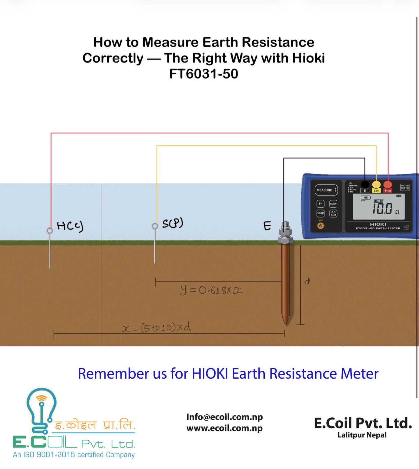
The Correct Method: Fall-of-Potential (Three-Pole Method)
The most reliable method for testing a single earth electrode is the three-pole fall-of-potential method.
In this setup, three connections are used.
- The first connection is E, which is connected to the earth electrode or earth pit being tested.
- The second connection is S (P), which is the potential probe placed in the soil to measure the voltage drop created by the test current.
- The third connection is H (C), which is the current probe used to inject current into the ground during the test.
- All three probes must be placed in a straight line across open ground so that the test current flows through the soil in a predictable path.
It is important that there are no buried metallic structures between the probes. Underground cables, water pipes, reinforcing bars, or nearby earth electrodes can distort the current path and cause incorrect readings.
Proper Probe Spacing
Correct probe spacing is essential for obtaining a reliable measurement.
A common rule used in field testing is based on the depth of the earth electrode.
- The distance between the earth electrode (E) and the current probe (H) should normally be around five to ten times the depth of the earth pit.
- The potential probe (S or P) is placed at approximately sixty-two percent of that distance from the earth electrode. This method is commonly referred to as the 62 percent rule.
This spacing helps ensure that the voltage measurement is taken in the correct region of the soil where the current distribution is stable.
Verifying the Measurement
A single reading should never be considered final. To confirm that the measurement is valid, the potential probe should be moved slightly and the test repeated.
Typically, three readings are taken.
- The first reading is taken when the potential probe is placed at roughly fifty-two percent of the distance between the earth electrode and the current probe.
- The second reading is taken at sixty-two percent, which is the main measurement point.
- The third reading is taken at around seventy-two percent of the distance.
If the values obtained from these three positions remain within plus or minus five percent, the measurement can be considered reliable.
Conditions That Affect the Accuracy of Earth Resistance Testing
Several environmental and installation factors can significantly influence earth resistance readings.
The test should be carried out on natural soil, not on concrete, asphalt, or tiled surfaces. Natural soil allows proper current flow through the ground during the test.
Slightly moist soil conditions are generally acceptable, but extremely wet soil immediately after heavy rainfall can produce misleading readings.
The earth electrode being tested should also be isolated from other grounding connections. If it remains connected to a grounding network, the tester will measure the combined resistance of the entire grounding system rather than the individual electrode.
Test leads should be stretched out properly across the ground. They should not be coiled or placed on top of each other, as this can introduce interference and measurement errors.
It is also good practice to record the soil condition, weather conditions, and probe spacing during the test. These details can be important when comparing results in future inspections.
Common Mistakes Seen on Site
Several common mistakes are frequently observed during field measurements.
- One of the most frequent issues is placing the probes too close to the earth electrode. When this happens, the electrical fields around the probes overlap, which often results in an artificially low resistance value.
- Another common mistake is placing the probes in a curved or irregular line instead of a straight line. This causes the current path to bend, which affects the voltage measurement.
- Nearby metallic structures can also interfere with the test. Buried cables, pipelines, or structural steel can create alternate current paths that distort the measurement.
- Testing immediately after rainfall can also be misleading. Surface water temporarily lowers soil resistance, giving a reading that may not represent normal operating conditions.
Finally, many technicians forget to isolate the earth pit before testing. In such cases, the tester measures the resistance of the entire grounding network rather than the individual electrode.
Why Accurate Earth Resistance Measurement Matters
The resistance value of a grounding system determines how effectively fault current can be safely dissipated into the earth.
If the resistance is too high, fault current may not flow safely into the ground. Instead, it may travel through electrical equipment or exposed conductive parts, increasing the risk of equipment damage or electric shock.
Accurate earth resistance measurement is therefore essential for ensuring that grounding systems perform correctly during electrical faults.
Conclusion
Measuring earth resistance properly requires more than simply connecting a tester and recording the displayed number. Correct probe spacing, proper alignment, suitable soil conditions, and careful testing procedures are all necessary to obtain reliable results.
Following the fall-of-potential method and verifying readings at multiple probe positions helps ensure that the measured resistance value truly represents the performance of the grounding system.
Spending a few extra minutes to perform the test correctly can make a significant difference in ensuring electrical safety and system reliability.